Terahertz General and High Level FET as a Detector
Terahertz Blog
This blog will deal with Terahertz issues some are internal work and others are pointing to good information that I found at the net.
General Background:
Great Lecture (unfortunately in Hebrew) by Dr. Evgeny Shumaker from IBM Haifa:
https://www.youtube.com/watch?v=dBNNfKiGI18
From Terahertz Gap at Wikipedia:
https://en.wikipedia.org/wiki/Terahertz_gap
In General the THZ Gap is based on the physical issue that the
FET As a Detectors:
The Basic article by Michel I Dyakonov and Michael S. Shur:
‘Plasma Wave Electronics: Novel Terahertz Devices using Two Dimensional Electron Fluid’
But let me put it a bit simplifier:
Please find in below schematic diagram of a single MOSFET, in case that the MOSFET is working at the ohmic region (No VDD) and ZCgs ->0 than VGS at THz =~VDS THz and then the FET act as a Mixer:
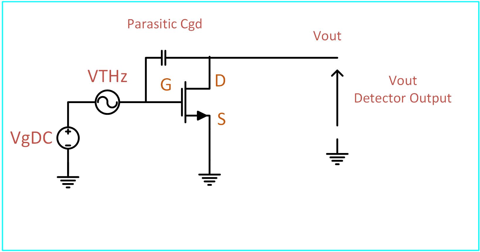
Ids(t)=W/L*μ*Coxide[(VgDC+VTHz(t)-Vth-Vds(t)/2]*Vds(t)
Where VgDC = Vgate DC- Gate DC Voltage , VTHz= V Gate THz , VTh= FET Threshold Voltage , Vds = Drain to Source Volatge, W= Junction Width, L =Junction Length, Coxoide = Gate to Channel Oxide Capacitor
In case that Vgs THz=~ VDs THz than:
Ids(t)=W/L*μ*Coxide[VTHz^2 (t)/2+(VgDC-Vth)*VTHz(t)]
The right side of the equation is a linear term and not part of the mixing operation, the left side of the equation have a quadrature component that act like a mixer.
Meaning that if:
VTHz(t)=A*cos(ω*t)
Than by the famous trig equation:
VTHz^2 (t)=A/2(1+cos(2ω*t))
The left side is a DC component that proportional to the THz Amplitude, and the right side is filtered.
Leave a Reply